|
|
Network Cable Standards DeMistified!!!
Moving more towards the networking stuff, here is something which is more essential - something which is always asked in our Orals during exams. Some standards of the Network Cables.. 10Base2
An Institute of Electrical and Electronic Engineers (IEEE) standard for implementing 10 megabits per second (Mbps) Ethernet over thin coaxial cabling. Overview10Base2 is based on the 802.3 specifications of Project 802 developed by the IEEE. It was ratified as an IEEE standard in 1985 and quickly found its way into corporate networks for small local area networks (LANs) connected to larger 10Base5 backbones. 10Base2 is sometimes referred to as thinnet or thin coax because it uses thin coaxial cabling for connecting stations to form a network (as compared to 10Base5, which uses a thicker form of cabling and hence is called thicknet). The designation 10Base2 is derived from the network’s speed (10 Mbps), the signal transmission method (baseband transmission), and the maximum segment length (185 meters, rounded off to 200 with the zeros removed). Another popular nickname for this technology was Cheapernet because thinnet cabling was considerably less costly than thicknet cabling. Implementation10Base2 networks are wired together using a bus topology, in which individual stations (computers) are connected directly to one long cable. The maximum length of any particular segment of a 10Base2 network is 607 feet (185 meters). If distances longer than this are required, two or more segments must be connected using repeaters. Altogether, a total of five segments can be connected using four repeaters, as long as only three of the segments have stations (devices) attached to them. This is referred to as the 5-4-3 rule. A 10Base2 segment should have no more than 30 stations wired to it. The minimum distance between these stations is 1.6 feet (0.5 meters). Stations are attached to the cable using BNC ( British Naval Connector or Bayonet-Neill-Concelman) connectors, and the ends of the cabling have BNC cable connectors soldered or crimped to them. 10Base2 supports a maximum theoretical bandwidth of 10 Mbps, but in actuality the presence of collisions reduces this to more like 4 to 6 Mbps. 10Base2 networks are not deployed much anymore for two reasons. First, because their speed is limited to 10 Mbps, the networks perform poorly in today’s bandwidth-hungry, Internet-connected world. Second, 10Base2 networks have a single point of failure—the long, linear bus cable used to connect the stations. A single break or loose connection brings down the entire network, thus every cable segment and station connection must be checked to determine the problem. If you are wiring an office for a small LAN with low bandwidth requirements, use 10BaseT instead, which is easier to manage and troubleshoot. For moderate to high bandwidth requirements, try using Fast Ethernet instead. The two ends of a 10Base2 bus must be properly terminated. If they are not, signals will bounce and network communication will come to a halt. 10Base5 An Institute of Electrical and Electronic Engineers (IEEE) standard for implementing 10 megabits per second (Mbps) Ethernet over coaxial cabling. Overview
10Base5 is based on the again on 802.3 specifications of Project 802 developed by the IEEE. It was developed as a standard in the early 1980s (I believe before 10Base2) and became hugely popular in corporate and campus networks. An earlier form of 10Mbps Ethernet developed by the DIX Consortium was superseded by 10Base5 when the IEEE 802.3 standard was created in 1983. 10Base5 is sometimes referred to as Thicknet because it uses thick coaxial cabling for connecting stations to form a network (compared to 10Base2, which uses a thinner form of cable and is hence called thinnet). Another name for 10Base5 is Standard Ethernet because it was the first type of Ethernet to be implemented (it is also sometimes referred to as Original Ethernet, for obvious reasons). The designation 10Base5 is derived from the network’s speed (10 Mbps), the signal transmission method (baseband transmission), and the maximum segment length (500 meters). Implementation
10Base5 networks are wired together in a bus topology—that is, in a linear fashion using one long cable. The maximum length of any particular segment of a 10Base5 network is 1640 feet (500 meters). If distances longer than this are required, two or more segments must be connected using repeaters. Altogether, there can be a total of five segments connected using four repeaters, as long as only three of the segments have stations (computers) attached to them. This is referred to as the 5-4-3 rule. A 10Base5 segment should have no more than 100 stations wired to it. These stations are not connected directly to the cable as in 10Base2 networks. Instead, a transceiver is attached to the cable, usually using a cable-piercing connector called a vampire tap. From the transceiver, a drop cable is attached, which then connects to the network interface card (NIC) in the computer. The minimum distance between transceivers attached to the cable is 8 feet (2.5 meters), and the maximum length for a drop cable is 164 feet (50 meters). Thicknet cable ends can have N-series connectors soldered or crimped on them for connecting segments together. 10Base5 was often used for backbones for large networks. In a typical configuration, transceivers on the thicknet backbone would attach to repeaters, which would join smaller thinnet segments to the thicknet backbone. In this way a combination of 10Base5 and 10Base2 standards could support sufficient numbers of stations for the needs of a moderately large company. 10Base5 supports a maximum bandwidth of 10 Mbps, but in actual networks, the presence of collisions reduces this to more like 4 to 6 Mbps. 10Base5 networks are legacy networks that are no longer being deployed, although some companies might choose to maintain existing ones for cost reasons. The complexity and bandwidth limitations of 10Base5 networks render them largely obsolete. If you are wiring an office for a small local area network (LAN) with low bandwidth requirements, use 10BaseT instead. For moderate to high bandwidth requirements, try using Fast Ethernet. If you are implementing a backbone for today’s high-speed enterprise networks, Gigabit Ethernet (GbE) is now the preferred technology. 10BaseF
An Institute of Electrical and Electronic Engineers (IEEE) standard for implementing 10 megabits per second (Mbps) Ethernet over fiber-optic cabling. Overview
10BaseF is based on the 802.3 specifications of Project 802 developed by the IEEE and differs from other forms of 10-Mbps Ethernet by using fiber-optic cabling instead of copper unshielded twisted-pair (UTP) cabling. The designation 10BaseF is derived from the network’s speed (10 Mbps), the signal transmission method (baseband transmission), and the physical media used (fiber-optic cabling). The 10BaseF standard actually consists of three separate standards describing different media specifications: - 10BaseFB: Defines how the synchronous data transmission occurs over the fiber-optic cabling. Using 10BaseFB segments, you can cascade or link synchronous fiber-optic hubs in configurations that are longer than traditional 10BaseT Ethernet networks and contain up to 1024 stations. This standard is more expensive and is not as widely implemented as 10BaseFL.
- 10BaseFL: Defines the characteristics of the fiber-optic link between the nodes and the hub or concentrator. 10BaseFL replaces the older standard for fiber-optic link segments, Fiber-Optic Inter-Repeater Link (FOIRL) segments, which was developed in the 1980s. 10BaseFL is the most commonly implemented version of 10BaseF.
- 10BaseFP: Defines the implementation of a star topology that does not use repeaters. 10BaseFP stands for Fiber Passive, and its segments can be only 500 meters (1640 feet) in length with a maximum of 33 stations connected. This standard is rarely used today.
Implementation
10BaseF is similar to 10BaseT in that each station is wired into a hub in a star topology to form the network. The maximum length of any segment of 10BaseF fiber-optic cabling is 6600 feet (2000 meters), compared to the 328 feet (100 meters) supported by 10BaseT, making 10BaseF suitable for long-haul interconnects. The recommended cabling type for 10BaseF networks is 62.5-micron diameter fiber-optic cabling. This cable can be terminated with either ST connectors or SMA connectors, depending on the vendor and the hub configuration. Two-strand multimode fiber-optic cabling is used, with one strand allotted for transmitting data and the other for receiving data. 10BaseF is preferable to 10BaseT in environments that are electrically noisy, such as in industrial areas, near elevator shafts, or around other motors or generators. Fiber-optic cabling is often used for running cables between buildings. Differences in ground potential between the ends of copper cabling can induce voltages that can damage networking equipment if the ends are not grounded properly. Fiber-optic cabling also supports faster speeds than copper UTP cabling and provides a more suitable upgrade option to Fast Ethernet and beyond. The maximum signal loss or attenuation on a given segment should be no more than 12.5 decibels. Using too many connectors in a segment of fiber-optic cabling can cause the attenuation to exceed this figure, which can lead to signal loss. 10BaseT
An Institute of Electrical and Electronic Engineers (IEEE) standard for implementing 10 megabits per second (Mbps) Ethernet over twisted-pair cabling. Overview
10BaseT is based on the 802.3 specifications of Project 802 developed by the IEEE and is the most popular form of 10-Mbps Ethernet. 10BaseT is deployed over structured cabling systems consisting of unshielded twisted-pair (UTP) cabling used for connecting end stations to centralized hubs to form a network. (Shielded twisted-pair [STP] cabling can also be used, but it never is.) The designation 10BaseT comes from the network’s speed (10 Mbps), the signal transmission method (baseband transmission), and the physical medium used for transmission (twisted-pair cabling). 10BaseT became widely popular because of the earlier success of the Public Switched Telephone Network (PSTN), a hierarchical structured-wiring system to which 10BaseT bears many similarities. An advantage of 10BaseT over earlier 10 Mbps Ethernet systems such as 10Base5 and 10Base2 is that it is easier to manage because of the centralization of network traffic in hubs. Implementation
In10BaseT networks, end stations such as workstations and servers are wired together in a star topology to a central hub. The UTP cabling used for wiring should be Category 3 (Cat3) cabling, Category 4 (Cat4) cabling, or Category 5 (Cat5) cabling, terminated with RJ-45 connectors. Patch panels can be used to organize wiring and provide termination points for cables running to
wall plates in work areas. Patch cables then connect each port on the patch panel to the hub. Usually most of the wiring is hidden in a wiring cabinet and arranged on a rack for easy access.
The maximum length of any particular segment of a 10BaseT network is 328 feet (100 meters). In practice this is not a limitation because a survey by AT&T indicated that about 99 percent of desktops in commercial buildings are located within 328 feet (100 meters) of a wiring closet. If distances longer than that are required, two or more segments may be connected using repeaters. The minimum length of any given segment is restricted to 8 feet (2.5 meters).
By using stackable hubs or by cascading regular hubs into a cascaded star topology, you can network large numbers of computers using 10BaseT cable. Although 10BaseT can support up to 1024 nodes, networks with no more than 200 or 300 nodes will yield the best performance
by keeping collision domains small. Hubs can be hierarchically arranged to a depth of up to three levels in order to accommodate much larger networks, but performance declines significantly as the number of stations exceeds several hundred.
Although 10BaseT theoretically supports a maximum bandwidth of 10 Mbps, in actual networks the presence of collisions reduces throughput to about 4 to 6 Mbps. The maximum length of a 10BaseT cable segment is not a result of the specifications for round-trip communications
on an Ethernet network but rather a limitation caused by the relatively low signal strength of 10BaseT systems. With enhanced Category 5 (Cat5e) cabling, you might be able to sustain network communications effectively with cable lengths up to about 490 feet (150 meters), although this is not normally recommended. 100BaseFX
An Institute of Electrical and Electronics Engineers (IEEE) standard for implementing 100 megabits per second (Mbps) Ethernet over fiber-optic cabling. Overview
100BaseFX is based on the 802.3u standard, which is an extension of the 802.3 standard of Project 802 developed by the IEEE. It’s a type of Fast Ethernet that is often used for wiring campus backbones using fiber-optic cabling. The designation 100BaseFX is derived from the network’s speed (100 Mbps), the signal transmission method (baseband transmission), and the physical medium used for transmission (fiber-optic cabling). Implementation
100BaseFX networks are wired together in a star topology using fiber-optic cabling and 100-Mbps fiber-optic hubs or Ethernet switches. 100BaseFX systems may be interconnected with 100BaseTX, 100BaseT4, and 10BaseT systems using auto negotiating hubs and switches with suitable ports. Two-strand fiber-optic cabling is required, and ST, SC, and MIC connectors are all supported. Signaling is at 125 megahertz (MHz), which when combined with the 80 percent efficiency of the 4B5B line coding mechanism used results in an overall transmission speed of 100 Mbps. The maximum length of any segment of fiber-optic cabling connecting a station (computer) to a hub in 100BaseFX is 1350 feet (412 meters), and not 1480 feet (450 meters) as some sources indicate. The grade of fiber-optic cabling used is usually two-strand multimode fiber-optic cabling, with one strand carrying transmitted data and the other strand receiving data. However, you can also use two-strand single-mode fiber-optic cabling. If multimode fiber-optic cabling is used, the variety used is typically a grade with a 62.5-micron core diameter.
Repeaters can be used to extend the length of cabling and for interfacing between 100BaseFX/TX and 100BaseT4 segments. The maximum allowable distances with repeaters are 2 kilometers using multimode fiber-optic cabling and 10 kilometers using singlemode
fiber-optic cabling. Only one or two repeaters can be used per collision domain, depending on
whether Class I or Class II repeaters are used. 100BaseFX and a related standard, 100BaseTX, are sometimes collectively referred to as 100BaseX. When using 100BaseFX with repeaters for backbone cabling runs, Ethernet switches cannot be more than 1350 feet (412 meters) apart when running in halfduplex mode and 6600 feet (2000 meters) apart when running in full-duplex mode. 100BaseT4
An Institute of Electrical and Electronics Engineers (IEEE) standard for implementing 100 megabits per second (Mbps) Ethernet over twisted-pair cabling. Overview
100BaseT4 is based on 802.3u, which is an extension of the 802.3 specifications of Project 802 developed by the IEEE. 100BaseT4 is the most commonly used implementation of Fast Ethernet today. The designation 100BaseT4 is derived from the network’s speed (100 Mbps), the signal transmission method (baseband transmission), and the physical medium used for transmission (all four pairs of wires in standard twisted-pair cabling). 100BaseT4 is now considered legacy technology and has been largely superseded by 100BaseTX. Implementation
100BaseT4 networks are wired together in a star topology using unshielded twisted-pair (UTP) cabling and 100-Mbps hubs or Ethernet switches. The UTP cabling involved may be Category 3 (Cat3), Category 4 (Cat4), or Category 5 (Cat5) cabling—with Cat5 cabling and enhanced Category 5 (Cat5e) cabling being the most commonly used solutions nowadays. 100BaseT4 uses all four pairs of wire in standard UTP cabling, for signaling with signaling rates of 25 megahertz
(MHz) and an 8B6T line coding mechanism. One pair is used exclusively for transmission and a second pair for reception. The other two pairs are bidirectional and can be used either to transmit or to receive data as required. In this way, three of the four wire pairs are used at any given time to provide half-duplex transmission or reception of signals. Sharing three pairs of wires for data transfer allows 100BaseT4 to make use of lower-grade Cat3 cabling already installed in many older buildings. The maximum length of any segment of cabling connecting
a station (computer) to a hub is 328 feet (100 meters). This ensures that round-trip signaling specifications are met, because violating these specifications can produce late collisions that disrupt network communications. The Electronic Industries Alliance/Telecommunications
Industry Association (EIA/TIA)– recommended length of cabling between the station and the wiring closet is only 295 feet (90 meters), allowing up to 32 feet (10 meters) more of cabling for patch cables used to connect patch panels to hubs or switches. The pinning of the RJ-45 connectors used for 100BaseT4 wiring is the same as for 10BaseT wiring.
Make sure all your cabling, connectors, and patch panels are fully Cat5-compliant. For example, ensure that when UTP cabling is connected to patch panels, wall plates, or connectors, the wires are not untwisted more than half an inch at the termination point. 100BaseT4 hubs and switches are typically available in an autosensing 10/100-Mbps variety for interoperability
with older 10BaseT networks and to facilitate an easy upgrade from 10BaseT to 100BaseT. 100BaseTX
An Institute of Electrical and Electronics Engineers (IEEE) standard for implementing 100 megabits per second (Mbps) Ethernet over twisted-pair cabling. Overview
100BaseTX is based on 802.3u, which is an extension of the 802.3 specifications of Project 802 developed by the IEEE. The designation 100BaseTX is derived from the network’s speed (100 Mbps), the signal transmission method (baseband transmission), and the physical medium used for transmission (the same two pairs of wires in standard four-wire twisted-pair cabling that are
used for 10BaseT Ethernet). Implementation
100BaseTX networks are wired together in a star topology using either unshielded twisted-pair (UTP) cabling or data-grade shielded twisted-pair (STP) cabling. If UTP cabling is used (which is the most common scenario), it must be Category 5 (Cat5) cabling or enhanced Category 5 (Cat5e) cabling. Stations are connected together using hubs or switches. Unlike 10BaseT hubs, which can be hierarchically connected up to three levels deep, 100BaseTX hubs can only be
connected two layers deep, which imposes additional distance limitations and may necessitate rewiring of existing cabling before upgrading from 10BaseT to 100BaseTX. 100BaseTX uses the two pairs of wires in twistedpair cabling that are used by 10BaseT networks, with one pair of wires used for transmission and the other used for reception. With the appropriate equipment, 100BaseTX is capable of supporting both the familiar half-duplex Ethernet used by 10BaseT and newer full-duplex Ethernet signaling technologies. 100BaseTX employs a signaling rate of 125 megahertz (MHz) for each pair of wires, which, because the 4B5B line coding algorithm used is only 80 percent efficient, translates into a data transmission speed of 100 Mbps. The maximum length of any segment of cabling connecting a station to a hub is 328 feet (100 meters). This ensures that round-trip signaling specifications are met, because violating these specifications can produce late collisions that disrupt network communications. The pinning of the RJ-45 connectors used for 100BaseTX wiring is the same as for 10BaseT wiring with wires 1 and 2 used for transmission and wires 3 and 6 used for reception. This enables 100BaseTX autosensing hubs and switches to operate in mixed 10/100 Mbps Ethernet networks.
The maximum distance between 100BaseTX hubs and bridges or switches is 738 feet (225 meters), further than the maximum hub-station distance of only 328 feet (100 meters).
100BaseTX and a related standard, 100BaseFX, are sometimes collectively referred to as 100BaseX. Although the maximum length of segments joining stations to hubs is 328 feet (100 meters), the Electronic Industries Alliance/Telecommunications Industry Alliance (EIA/TIA) recommends only 295 feet (90 meters) of cabling between the station (computer) and the wiring closet, allowing up to 32 feet (10 meters) more of cabling for patch cables used to connect patch panels to hubs or switches.
Tech.ED 2005 @ India
One of the most happening events by Microsoft India, Tech.ED is back. Tech•Ed 2005 is Microsoft's largest technology educational conference. Meet
thousands of your peers. Discuss the challenges you face in the industry.
Explore solutions with the experts behind the technology you use every day. Add
value to your company's IT investments. However this time its two monts earlier then last year. It kicks off from June 14 at Banglore and by the time its July 2, its already travelled 5 Cities and is at final destination New Delhi. This year TechED brings 3 more additional tracks than the previous year. The tracks are as follows: Smart Client & Connected Systems IT Professionals Developer Tools Database Mobile & Embedded Architects The additional ones are Smart Clients & Connected Systems, Mobile & Embedded and the most happening one Architechs. The complete schedule of TechED is available here. There are also early bird offers which give you a handsome discount upto 1500 bucks :) So get connected and get TechED.
Crimson Skies : Road to Revenge Review

Well being hooked onto Xbox for over a week now, I really loved playing Crimson Skies: Road to Revenge. One of the tabletop stratege game, it stars Nathan Zachary, a rugged and handsome leader of the Fortune Hunters, a Robin Hood--style air pirate gang with hearts of gold, flying the unfriendly skies in 1930s - America. The nation has been split into warring factions, and fighter planes and the zeppelins battle for supremacy on a daily basis. Every character is indeed a real character, and the game flows with bravado and a winking sense of humor---thanks in no small part to the superlative voice acting. It is Natan's rival, come to collect the spoils of a high stakes card game gone awry, including a Devastator dog fighter and Nathan's zeppelin, the Pandora. Being a man of action, he does what any self-respecting air pirate would do, stealing back his plane in short order thanks to some proficient wing-walking. His teammate Betty helps him retrieve the zeppelin in what amounts to a quick tutorial, leaving only the task of finding Big John, a competent pilot to take the Pandora's helm. More search finds, scientist named Dr. Fassenbiender. The doctor was being forced to work for the Germans, until his refusal to develop destructive technology for them landed him a spot next to Nathan in a POW camp. The doctor believes it is Von Essen, a mad German scientist who began work on using the technology for use as a weapon. With this in mind, the doctor gives Nathan the blueprints to keep his research safe. What follows is a story of intrigue, betrayal, and exploration, as you attempt to overcome impossible odds to save the world from tyranny. 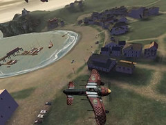
The fighters are controlled using the left stick to steer, and the right to perform barrel rolls. The cruising speed is dependant on what plane you are in, but is generally constant. If a need arises for speed, you can hit Y for a quick boost, and holding B allows you to brake for quick turns. The right trigger is used to fire primary weapons like machine guns and cannons, while the left launches secondaries including rockets and fireball cannons. The D-pad is used to take a look around, or you can hold the Black button to lock the view onto a nearby enemy. If you're in the mini-gyro or a turret, pressing A zooms the view so you can accurately aim at distant targets. Flying high was always though, as some missions involved manning anti-aircraft guns to defend a location from swarms of fighters. There are a few different types of gun emplacements, including dual cannons, four rapid-fire machine guns, a rocket launcher, and a guided missile you can arc over mountains. If in a vehicle with multiple turrets, you can press Y and B to cycle through them, allowing you to use an array of weapons from various positions as you see fit. The main interface was clean as it gets, consisting of Game Demos, Multiplayer, and Single Player selections. Entering the Single Player menu gave a list of active pilots which I could pick to continue my quest and an option to create a new profile. Creating a new pilot required minimal effort: simply entering a name, a few settings, and Woila. Vibration could be turned on/off by inverting the Y-axis, set three sound levels, and pick a difficulty, making for a simple, albeit bare options menu. In and all, love the game and also the XBox. Sadly I have to return this back to Microsoft today. Wish I could buy one for myself. Lets hope XBox 2 brings on more cheers and smiles on my face.
XBox Green Reviewed
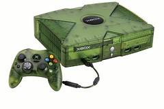
Recently, thanks to Abhishek, I was able to have a nice look at the Green Xbox console. Here is a small review of it. Hope you ppl like it.. This one is a Limited Edition Xbox console and is translucent green in color. It came it with a translucent green (S) type controller. This has stunning graphics and immense power under the hood, so much that your screen doesnt even flicker, even if you have tri-linear, bump mapping and shadows turned on. Its paked up with 733MHz processor, 64MB of Memory, 8 gigabyte hard drive, built-in ethernet port, and NVIDIA graphics processing unit. This surely is one sort of HIGH end console, something which you are compelled to drool over. This gives you power like P4 2.5 Ghz machine with lots of memory and GeForce3 GPU. Its something like, a Final Fantansy movie, right in front of you. The system also supports DVD playback and boasts 256 bit audio channels - supporting Dolby Digital and Dolby Surround - which all combine to give you an unrivalled audio experience. Three Cheers to XBox. Its purely a mean gammin machine.
Some Common Networking Protocols
Here are some common Networking Protocols. Somethings which is essential for the MSCE exam 70-058 and also as a basic networking knowledge.Network Basic Input/Output System (NetBIOS) Most of the services and applications that run within the Windows operating system use the NetBIOS interface or interprocess communication (IPC). NetBIOS was developed on LANs and has evolved into a standard interface for applications to use to access networking protocols in the transport layer for both connection-oriented and nonconnection-oriented communications. NetBIOS interfaces exist for NetBEUI, NWLink, and TCP/IP. NetBIOS requires an IP address and a NetBIOS name to uniquely identify a computer. NetBIOS performs four primary functions: - NetBIOS name resolution Each workstation on a network has one or more names. NetBIOS maintains a table of the names and any aliases. The first name in the table is the unique name of the NIC. Optional user names can be added to provide a user-friendly identification system. NetBIOS then cross-references the names as required.
- NetBIOS Datagram service This function allows a message to be sent to any name, group of names, or to all users on the network. However, because this does not use point-to-point connections, there is no guarantee that the message will arrive at its destination.
- NetBIOS Session service This service opens a point-to-point connection between two workstations on the network. One workstation initiates a call to another and opens the connection. Because both workstations are peers, they both can send and receive data concurrently.
- NetBIOS NIC/session status This function makes information about the local NIC, other NICs, and any currently active sessions available to any application software using NetBIOS.
Originally, IBM offered NetBIOS as a separate product, implemented as a terminate-and-stay-resident (TSR) program. This TSR program is now obsolete; if you should encounter one of these systems, you should replace it with the Windows NetBIOS interface.
NetBEUINetBEUI is the acronym for NetBIOS Extended User Interface. Originally, NetBIOS and NetBEUI were tightly tied together and considered one protocol. However, several network manufacturers separated out NetBIOS, the session-layer protocol, so that it could be used with other routable transport protocols. NetBIOS (network basic input/output system) is an IBM session-layer LAN interface that acts as an application interface to the network. NetBIOS provides the tools for a program to establish a session with another program over the network and, because so many application programs support it, it is very popular. NetBEUI is a small, fast, and efficient transport-layer protocol that is supplied with all Microsoft network products. It has been available since the mid-1980s and was supplied with the first networking product from Microsoft: MS-NET. Advantages of NetBEUI include its small stack size (important for computers running MS-DOS), its speed of data transfer on the network medium, and its compatibility with all Microsoft-based networks. X.25 Packet Switching
A set of WAN protocols, X.25 is incorporated in a packet-switching network made up of switching services. The switching services were originally established to connect remote terminals to mainframe host systems. The network breaks up each transmission into multiple packets and places them on the network. The pathway between nodes is a virtual circuit that looks like a single, continuous, logical connection to the upper layers. Each packet can take different routes from the source to the destination. After the packets arrive, they are reassembled into their original data message. A typical packet includes 128 bytes of data; however, the source and destination can negotiate a different packet size after making the virtual connection. The X.25 protocol can support a theoretical maximum of 4095 concurrent virtual circuits across a physical link between a node and the X.25 network. Typical data-transmission speed for X.25 is 64 Kbps. The X.25 protocol works in the physical, data-link and network layers of the OSI reference model. It has been around since the mid-1970s and has been well debugged; therefore, it is a stable network environment. It does, however, have two shortcomings: - The store-and-forward mechanism causes delays. Typically, the delay is about .06 second and has no effect on large blocks of data. However, in a flip-flop type of transmission, the delay might be noticeable.
- A large amount of buffering is required to support the store-and-forward data transfer
X.25 and TCP/IP are similar in that they both use packet-switched protocols. However, there are several differences between the two: - TCP/IP has only end-to-end error checking and flow control; X.25 has error checking from node to node.
- To compensate for the fact that a TCP/IP network is completely passive, TCP/IP has a more complicated flow control and window mechanism than X.25 has.
- X.25 has tightly specified the electrical and link levels; TCP/IP is designed to travel over many different kinds of media, with many different types of link service.
Xerox Network System (XNS)
Xerox developed Xerox Network System (XNS) for its Ethernet LANs. XNS became widely used in the 1980s, but has been slowly replaced by TCP/IP. It is a large, slow protocol, but produces more broadcasts, causing more network traffic.
Advanced Program-to-Program Communication (APPC)
Advanced Program-to-Program Communication (APPC ) is IBM's transport protocol developed as part of its Systems Network Architecture (SNA). It was designed to enable application programs running on different computers to communicate and exchange data directly. AppleTalk
AppleTalk is Apple Computer's proprietary protocol stack designed to enable Apple Macintosh computers to share files and printers in a networked environment. It was introduced in 1984 as a self-configuring LAN technology. AppleTalk is also available on many UNIX systems that use third-party freeware and commercial packages. The AppleTalk protocol suite encompasses high-level file sharing using AppleShare, LaserWriter printing services and print spoolers, along with lower-level data streams and simple datagram delivery.
OSI Protocol Suite
The OSI protocol suite is a complete protocol stack. Each protocol maps directly to a single layer of the OSI reference model. The OSI protocol suite includes routing and transport protocols, IEEE 802 series protocols, a session-layer protocol, a presentation-layer protocol, and several application-layer protocols designed to provide full networking functionality, including file access, printing, and terminal emulation.
DECnet
DECnet is Digital Equipment Corporation's proprietary protocol stack. It is a set of hardware and software products that implement the Digital Network Architecture (DNA). It defines communication networks over Ethernet LANs, Fiber Distributed Data Interface metropolitan area networks (FDDI MANs), and WANs that use private or public data-transmission facilities. DECnet can also use TCP/IP and OSI protocols as well as its own protocols. It is a routable protocol.
DECnet has been updated several times; each update is called a "phase." The current revision is DECnet Phase V, and the protocols used are both proprietary to Digital and offer a fairly complete implementation of the OSI protocol suite.
Introduction to TCP/IP
This is something which I learnt at College and also while preparing for MCSE.. Some basics about TCP/IPTCP/IP has become the standard protocol used for interoperability among many different types of computers. This interoperability is a primary advantage of TCP/IP. Most networks support TCP/IP as a protocol. TCP/IP also supports routing and is commonly used as an internetworking protocol. Other protocols written specifically for the TCP/IP suite include: - SMTP (Simple Mail Transfer Protocol) E-mail.
- FTP (File Transfer Protocol) For exchanging files among computers running TCP/IP.
- SNMP (Simple Network Management Protocol) For network management.
Designed to be routable, robust, and functionally efficient, TCP/IP was developed by the United States Department of Defense as a set of wide area network (WAN) protocols. Its purpose was to maintain communication links between sites in the event of nuclear war. The responsibility for TCP/IP development now resides with the Internet community as a whole. TCP/IP requires significant knowledge and experience on the user's part to install and configure. Using TCP/IP offers several advantages; it: - Is an industry standard As an industry standard, it is an open protocol. This means it is not controlled by a single company, and is less subject to compatibility issues. It is the de facto protocol of the Internet.
- Contains a set of utilities for connecting dissimilar operating systems Connectivity from one computer to another does not depend on the network operating system used on either computer.
- Uses scalable, cross-platform client-server architecture TCP/IP can expand (or shrink) to meet future needs and circumstances. It uses sockets to make the computer operating systems transparent to one another.
TCP/IP Standards
TCP/IP standards are published in a series of documents called Requests for Comment (RFC). Their primary purpose is to provide information or to describe work in progress. Although not originally intended to serve as standards, many RFCs are accepted as true standards.
Internet development is based on the concept of open standards. That is, anyone who wishes to do so can use or participate in developing standards for the Internet. The Internet Architecture Board (IAB) is the committee responsible for managing and publishing RFCs for the Internet. The IAB allows anyone or any company to submit or evaluate an RFC. This includes any proposed idea for changes or new standards. After a reasonable amount of time is allowed for discussion, a newly proposed draft will or will not become a standard.
The InterNIC Directory and Database provided by AT&T is a service that furnishes sources of information about the Internet to the public. The Directory and Database includes the RFCs. This service can be found at http://www.internic.net/ on the World Wide Web. Furthermore, RFCs can be downloaded from the following FTP sites: http://nis.nsf.net
http://ftp.ncren.net
http://ftp.sesqui.net
http://ftp.isi.edu
http://wuarchive.wustl.edu
http://ftp.imag.fr TCP/IP and OSI
The TCP/IP protocol does not exactly match the OSI reference model. Instead of seven layers, it uses only four. Commonly referred to as the Internet Protocol Suite, TCP/IP is broken into the following four layers: - Network interface layer
- Internet layer
- Transport layer
- Application layer
Each of these layers corresponds to one or more layers of the OSI reference model. Network Interface Layer
The network interface layer, corresponding to the physical and data-link layers of the OSI reference model, communicates directly with the network. It provides the interface between the network architecture (such as token ring, Ethernet) and the Internet layer. Internet Layer
The Internet layer, corresponding to the network layer of the OSI reference model, uses several protocols for routing and delivering packets. Routers, are protocol dependent. They function at this layer of the model and are used to forward packets from one network or segment to another. Several protocols work within the Internet layer.
Internet Protocol (IP)
Internet Protocol (IP) is a packet-switched protocol that performs addressing and route selection. As a packet is transmitted, this protocol appends a header to the packet so that it can be routed through the network using dynamic routing tables. IP is a connectionless protocol and sends packets without expecting the receiving host to acknowledge receipt. In addition, IP is responsible for packet assembly and disassembly as required by the physical and data-link layers of the OSI reference model. Each IP packet is made up of a source and a destination address, protocol identifier, checksum (a calculated value), and a TTL (which stands for "time to live"). The TTL tells each router on the network between the source and the destination how long the packet has to remain on the network. It works like a countdown counter or clock. As the packet passes through the router, the router deducts the larger of one unit (one second) or the time that the packet was queued for delivery. For example, if a packet has a TTL of 128, it can stay on the network for 128 seconds or 128 hops (each stop, or router, along the way), or any combination of the two. The purpose of the TTL is to prevent lost or damaged data packets (such as missing e-mail messages) from endlessly wandering the network. When the TTL counts down to zero, the packet is eliminated from the network. Another method used by the IP to increase the speed of transmission is known as "ANDing." The purpose of ANDing is to determine whether the address is a local or a remote site. If the address is local, IP will ask the Address Resolution Protocol (ARP), discussed in the next section, for the hardware address of the destination machine. If the address is remote, the IP checks its local routing table for a route to the destination. If a route exists, the packet is sent on its way. If no route exists, the packet is sent to the local default gateway and then on its way. Address Resolution Protocol (ARP)
Before an IP packet can be forwarded to another host, the hardware address of the receiving machine must be known. The ARP determines hardware address (MAC addresses) that correspond to an IP address. If ARP does not contain the address in its own cache, it broadcasts a request for the address. All hosts on the network process the request and, if they contain a map to that address, pass the address back to the requestor. The packet is then sent on its way, and the new information address is stored in the router's cache. Reverse Address Resolution Protocol (RARP)
A RARP server maintains a database of machine numbers in the form of an ARP table (or cache) which is created by the system administrator. In contrast to ARP, the RARP protocol provides an IP number to a requesting hardware address. When the RARP server receives a request for an IP number from a node on the network, it responds by checking its routing table for the machine number of the requesting node and sending the appropriate IP number back to the requesting node. Internet Control Message Protocol (ICMP)
The ICMP is used by IP and higher-level protocols to send and receive status reports about information being transmitted. Routers commonly use ICMP to control the flow, or speed, of data between themselves. If the flow of data is too fast for a router, it requests that other routers slow down.
The two basic categories of ICMP messages are reporting errors and sending queries. Transport Layer
The transport layer, corresponding to the transport layer of the OSI reference model, is responsible for establishing and maintaining end-to-end communication between two hosts. The transport layer provides acknowledgment of receipt, flow control, and sequencing of packets. It also handles retransmissions of packets. The transport layer can use either TCP or User Datagram Protocol (UDP) protocols depending on the requirements of the transmission. Transmission Control Protocol (TCP)
The TCP is responsible for the reliable transmission of data from one node to another. It is a connection-based protocol and establishes a connection (also known as a session, virtual circuit, or link), between two machines before any data is transferred. To establish a reliable connection, TCP uses what is known as a "three-way handshake." This establishes the port number and beginning sequence numbers from both sides of the transmission. The handshake contains three steps: - The requestor sends a packet specifying the port number it plans to use and its initial sequence number (ISN) to the server.
- The server acknowledges with its ISN, which consists of the requestor's ISN, plus 1.
- The requestor acknowledges the acknowledgement with the server's ISN, plus 1.
In order to maintain a reliable connection, each packet must contain: - A source and destination TCP port number.
- A sequence number for messages that must be broken into smaller pieces.
- A checksum to ensure that information is sent without error.
- An acknowledgement number that tells the sending machine which pieces of the message have arrived.
- TCP Sliding Windows.
Ports, Sockets, and Sliding Windows
Protocol port numbers are used to reference the location of a particular application or process on each machine (in the application layer). Just as an IP address identifies the address of a host on the network, the port address identifies the application to the transport layer, thus providing a complete connection for one application on one host to an application on another host. Applications and services (such as file and print services or telnet) can configure up to 65,536 ports. TCP/IP applications and services typically use the first 1023 ports. The Internet Assigned Numbers Authority (IANA) has assigned these as standard, or default, ports. Any client applications dynamically assign port numbers as needed. A port and a node address together make up a socket. Services and applications use sockets to establish connections with another host. If applications need to guarantee the delivery of data, the socket chooses the connection-oriented service (TCP). If the applications do not need to guarantee data delivery, the socket chooses the connectionless service (UDP). A sliding window is used by TCP for transferring data between hosts. It regulates how much information can be passed over a TCP connection before the receiving host must send an acknowledgement. Each computer has both a send and a receive window that it utilizes to buffer data and make the communication process more efficient. A sliding window allows the sending computer to transmit data in a stream without having to wait for each packet to be acknowledged. This allows the receiving machine to receive packets out of order and reorganize them while it waits for more packets. The sending window keeps track of data that has been sent, and if an acknowledgement is not received within a given amount of time, the packets are re-sent. User Datagram Protocol (UDP)
A connectionless protocol, the UDP, is responsible for end-to-end transmission of data. Unlike TCP, however, UDP does not establish a connection. It attempts to send the data and to verify that the destination host actually receives the data. UDP is best used to send small amounts of data for which guaranteed delivery is not required. While UDP uses ports, they are different from TCP ports; therefore, they can use the same numbers without interference. Application Layer Corresponding to the session, presentation, and application layers of the OSI reference model, the application layer connects applications to the network. Two application programming interfaces (APIs) provide access to the TCP/IP transport protocols—Windows Sockets and NetBIOS.
Windows Sockets Interface
Windows Sockets (WinSock) is a networking API designed to facilitate communication among different TCP/IP applications and protocol stacks. It was established so that applications using TCP/IP could write to a standard interface. WinSock is derived from the original sockets that API created for the BSD Unix operating system. WinSock provides a common interface for the applications and protocols that exist near the top of the TCP/IP reference model. Any program or application written using the WinSock API can communicate with any TCP/IP protocol and vice versa.
PuneITPro UG Meet
It was 9.00 am in the morning of 10th April, 2004. A blissful Sunday, with the sun already out and shining. It was about 60 minutes for the session on Longhorn to start off. So I got ready and reached the Venue by 930 hrs.
Moments later, my cell rings. It was Manik Ahuja, IT Professional Evangelist, Microsoft Bangalore, on the line. He was also close to the venue and was asking me the last minute directions (since it was held at my college :)). Its about 0945 hrs now, and the session was to be started. However, the hall seemed margingly full and I was worried if people would turn up for the session or not. All I could see at that moment, were some students from various colleges across Pune, about 10-12 of them. They were really interested to know about Longhorn.
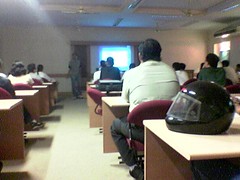
We (read: Manik and I) setup Manik's laptop and the project by around 0955 hrs. Few more people had come into the "Smart Room" and I was feeling relaxed about the audiance. More minutes pass by, about 1003 in the clock and we start the session. There are about 35 people now in the room.
To start of with, Manik showed an interesting video on Transition in Microsoft, from Windows 1.0 to 3.0 to 95 to 98 to 2000 to XP and then the most awaited Longhorn. This video, actually got the audiance into the groove of the session. Later on, Manik explained the audiance about the 3 pillers of Longhorn, viz. Avalon (the presentation SubSystem), Indigo (the programmers dream) and WinFX (a completely new file system built on top of NTFS). He also explained various facts about installation, which would take only about 15-20 min to install a DNS server. He also explained stuff about IIS 7.0, using a video, which would be shipping in as a feature of Longhorn. He also showed a video, of how you could install the Longhorn Server using the command prompt. So basically there was a lot of Gyan for all the System Admins present out there.
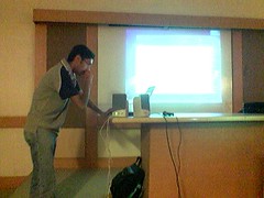
Not to leave some developers behind ( and ofcourse students), the onus came onto me. After Manik's nice and intersting talk about the Servers, I gave a demo about the Longhorn Client. It was actually fun telling people about the SideBar, a complete new Interface, the New Calender and stuff. So basically showed what is there in the Longhorn OS for people to watch out for and what features would it provide for the developers. Laterz, I take a back seat and Manik starts a nice Q&A session. Lots of question get answered, however, someone pops up a question on XAML.
I was planning to show an XAML basesd application which worked fine on my desktop, (Win XP with SP2, November CTP Download for Avalon and Whidbey Beta 1). Manik knew that I had some knowledge about XAML so he directed the question to me. However to my bad luck, the app did not work fine on Sarang's lappie. Not to fall back, I explained the XAML Code to ppl and told them steps on how to go about downloading it from the NET for their XP based machines.
Lastly we winded up the session by 11.30, and Manik was open to all the offline questions. However before winding up, Manik threw a surprise for all the attendies, that PuneITPro would be giving away a cool Grey MSN India t-shirts. It was a great surprise for all of them.
Before I forget, a great thanks to Anand Deodhar sir, for providing PuneITPro all the infrastructure for the session, without whom, the session wouldnt have taken
place.
Me on the talks ;)
Audiance 4
Win203 as Workstation - System Restore Feature
|
|


